We are all used now to twisted pair and fiber, and not everyone already recalls this time. But believe or not, the first media used for the Ethernet networks was the coaxial cable or coax. It remained as most common media for years, but has been recently replaced by twisted pair and fiber optics in modern LAN solutions. As seen from Figure 1. coaxial cable is made of conducting core in the middle (made of metal or copper) that is surrounded by an insulator, then by braided metal shielding and outer sheath cover.
Figure 1. Coaxial cable.
Core in the coax is made of solid metal wire or several thin wires. The core is carrying data in electromagnetic signals. In order to protect signal from the noise, the braided shielding is used. Also it acts as a ground for the signal. Insulator layer is between metal shielding and core, in order to prevent short-circuit. The insulator is made of plastic like PVC or Teflon. Also, plastic is used for external protection, and can differ based on price and qualities, such as fire-resistance.
Usage of many different materials for manufacturing makes coaxial cable more expensive than twisted pair. On the bright side, coaxial cable is able to transmit signal on longer distances without amplification compared to the twisted pair. Of course, it is losing in distance to fiber. Due to shielding, coaxial cable is having greater noise resistance.
While there are hundreds of different coaxial cables, main differences are in their impedance, attenuation, and throughput which change depending on the materials that are used for cable. Each type of coax is developed for its specific purpose.
Two most commonly used in networks cables are RG-6 (with copper core and is used for TV and Internet) and RG-59 (with braided copper core, used for short distribute connections). Those cables terminate with either F-Type connector or the BNC connector.
The F-Type connector is most often used with the RG-6 cables. It is attached to the cable, so the pin in the center of the connector is the conducting core of the cable. It is being attached by crimping or compression. Connectors can be screwed to each other for stable connection.
Figure 2 – F-type coaxial connector
The BNC (Bayonet Neill-Concelman) is also crimped, compressed, or twisted onto a coaxial cable. Two BNC connectors can be interconnected using turning-and-locking mechanism. Unlike F-type, BNC is using own conducting pin. Most commonly BNC is used with RG-59, but it can be also found on RG-6 sometimes.
Figure 3 – BNC-type coaxial connector
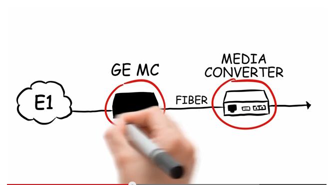
If not for Ethernet, then for Video CCTV applications coaxial cables and BNC connectors are still widely used. And interesting coexistence for a BNC and Fiber, is for example Video over Fiber series equipment, where BNC is used for input port for video and then it get’s converted and sent over the fiber.